
By the end of this guide you will have an LED blinking on and off every second — controlled by code you wrote yourself. You will understand the circuit, understand the code, and be ready to modify it for your own projects. This is the foundation of everything in Arduino and microcontroller programming. 🚀
🔴 What is Arduino Uno R3?
The Arduino Uno R3 is the world’s most popular microcontroller development board for beginners. It is based on the ATmega328P microcontroller running at 16 MHz with 5V logic — making it simple, forgiving, and compatible with thousands of sensors and modules available in Bangladesh.
Think of it as a small, programmable computer you can hold in your hand. You write code on your laptop using the free Arduino IDE software, click Upload, and the board runs your code — controlling LEDs, reading buttons, spinning motors, or reading sensors. No operating system to deal with. No complicated setup. Just code and hardware. 🛠️
The “R3” stands for Revision 3 — the third major design revision of the original Arduino Uno. It is the standard version you will find in most shops, tutorials, and courses. All the code in this guide works on R3.
| Specification | Arduino Uno R3 |
|---|---|
| Microcontroller | ATmega328P |
| Clock Speed | 16 MHz |
| Operating Voltage | 5V logic |
| Digital I/O Pins | 14 pins (6 with PWM) |
| Analog Input Pins | 6 pins (10-bit ADC) |
| Flash Memory | 32 KB |
| SRAM | 2 KB |
| Onboard LED | Pin 13 (built-in) |
Arduino Uno has a built-in LED on Pin 13. This means you can run your first blink project with zero external components — no LED, no resistor, no breadboard needed. Just the board, a USB cable, and your laptop. We will start with the built-in LED, then move to an external one.
🧰 What You Need
Here is everything you need to complete this project. The bare minimum (just the board and USB cable) gets you started with the built-in LED. Adding a breadboard and components lets you wire an external LED too.
| Component | Quantity | Required For |
|---|---|---|
| Arduino Uno R3 | 1 | ✅ Essential |
| USB Type-B Cable (or Type-C) | 1 | ✅ Essential |
| Computer with Arduino IDE 2 | 1 | ✅ Essential |
| LED (any colour) | 1 | For external LED |
| 220Ω or 330Ω Resistor | 1 | For external LED |
| Breadboard | 1 | For external LED |
| Jumper Wires (Male to Male) | 2 | For external LED |
You do not need a breadboard, resistor, or external LED to complete Step 1 of this guide. Arduino Uno has a built-in LED on Pin 13. Start there. Once your first blink works, then add the external LED and resistor for the second part of the tutorial.
💻 Install Arduino IDE
Arduino IDE is the free software you use to write and upload code to your Arduino Uno. Download Arduino IDE 2 — it is the newest version with autocomplete, better error messages, and a cleaner interface than the older 1.x. Both are free.
Both options give you the same free software. The Microsoft Store version updates automatically on Windows — handy for keeping things current without manual downloads.
⚙️ Setup Steps for Arduino Uno
- 1Install Arduino IDE 2
Download from one of the two links above. Run the installer and accept all defaults. Wait for the installation to complete — it only takes 1–2 minutes.
- 2Install the USB Driver
Most Arduino Uno R3 boards use a CH340G or ATmega16U2 USB chip. Dream RC’s product page lists which chip your board uses and includes the correct driver download link. Install it, then reboot your computer.
- 3Connect and Select Your Board
Plug your Arduino Uno into your computer via USB. In Arduino IDE, go to Tools → Board → Arduino AVR Boards → Arduino Uno. Arduino Uno is built into the IDE — no extra packages to install! 🎉
- 4Select the COM Port
Go to Tools → Port and select the port that appeared when you plugged in the board (e.g., COM3, COM5 on Windows). If no port appears, check the USB cable is a data cable (not charge-only) and the driver is installed correctly.
Unlike ESP32 which requires downloading a ~250 MB board package separately, Arduino Uno support is built directly into Arduino IDE. Select Arduino Uno from the board list and you are ready to upload. This is one reason Arduino Uno is genuinely simpler to set up than ESP32 for absolute first-timers.
⚡ Understand the Circuit
Part A — Using the Built-in LED (No Components Needed)
Arduino Uno R3 has a small yellow or green LED soldered directly onto the board, connected to Pin 13. When Pin 13 is set HIGH (5V), the LED turns on. When set LOW (0V), it turns off. You do not need any external components for this first step — just power the board via USB and the built-in LED will respond to your code.
Part B — Wiring an External LED
Once the built-in LED blink works, try connecting an external LED. You can use any digital pin (Pin 13, 9, 8, 7, etc.). Here is the wiring for Pin 13:
Replace this block with your Dream RC uploaded wiring diagram (PNG/WebP, 800×400px, white background)
📌 Wiring Instructions (External LED)
- Take a jumper wire and connect it from Pin 13 on the Arduino to a row on the breadboard
- Place your 220Ω resistor in series in that same row — one leg in the same row as the wire from Pin 13, other leg in a new empty row
- Place the LED anode (longer leg) in the same row as the second resistor leg
- Place the LED cathode (shorter leg) in a different row
- Take another jumper wire from the cathode row to GND on the Arduino
Connecting an LED directly to a GPIO pin without a resistor will draw too much current and can permanently damage the GPIO pin or burn out the LED. Always use a 220Ω or 330Ω resistor in series. It reduces the current to a safe level. This rule applies to every board — Arduino Uno, ESP32, Raspberry Pi — always. 🛡️
Longer leg = Anode (+) → goes toward the resistor (toward Pin 13). Shorter leg = Cathode (−) → goes toward GND. If your LED does not light up, try flipping it around — it simply will not work in the wrong direction but will not be damaged either.
📝 Write and Upload the Blink Code
Open Arduino IDE. Click File → New Sketch. Delete any default code that appears and paste in the following:
🔍 What Each Line Does
| Code | What It Does |
|---|---|
| const int LED_PIN = 13 | Creates a constant named LED_PIN with value 13. Using a named constant makes code easier to read and change. |
| void setup() | Runs once when the Arduino powers on. Used for one-time setup tasks like configuring pin modes. |
| Serial.begin(9600) | Opens serial communication at 9600 baud so you can see messages in the Serial Monitor window. |
| pinMode(LED_PIN, OUTPUT) | Tells Pin 13 that it will be an OUTPUT — meaning the Arduino controls the voltage on that pin. |
| void loop() | Runs forever in a continuous loop as long as the Arduino has power. Your main program logic goes here. |
| digitalWrite(LED_PIN, HIGH) | Sets Pin 13 to 5V — this turns the LED on by allowing current to flow through it. |
| delay(1000) | Pauses the program for 1000 milliseconds = 1 second. Change this number to change blink speed. |
| digitalWrite(LED_PIN, LOW) | Sets Pin 13 to 0V — this turns the LED off by stopping current flow. |
📤 How to Upload
- Make sure Arduino Uno is selected under Tools → Board
- Make sure the correct COM Port is selected under Tools → Port
- Click the Upload button (right-facing arrow in the toolbar)
- Watch the bottom console — you will see “Compiling sketch…” then “Uploading…”
- When you see “Done uploading” — the code is running ✅
- The LED on your Arduino Uno should now blink on and off every second. Open Tools → Serial Monitor, set baud to 9600, and watch “LED ON / LED OFF” messages appear. 🎉
🧪 Modify and Experiment
Congratulations — your LED is blinking! 🎉 Now let’s make it interesting. The best way to learn programming is to make small changes and see what happens. Try each of these modifications one at a time:
⚡ Experiment 1 — Change the Blink Speed
Find the two delay(1000) values and change both to 100. Upload again. The LED now blinks 10 times per second — much faster! Try different values: 2000 (very slow), 500 (half second), 50 (very fast flickering).
🔆 Experiment 2 — Different ON and OFF Times
Change the first delay (after HIGH) to 200 and the second delay (after LOW) to 800. Now the LED is ON for 0.2 seconds and OFF for 0.8 seconds. Interesting rhythm! Try making it flash like a camera: 50ms ON, 950ms OFF.
🆘 Experiment 3 — SOS Pattern
The SOS code introduced a custom function blink(duration) — your first step toward structured, reusable code. This is how real programs are built: break complex tasks into small, reusable functions. From here, the jump to more advanced Arduino projects is smaller than you think. 💪
⚠️ Common Errors and Fixes
Ran into a problem? These are the most common issues beginners face in Bangladesh with their first Arduino project:
Serial.begin(9600), set Serial Monitor to 9600 baud.Many cheap USB cables sold in Bangladesh markets carry power only — they cannot transfer data. If your computer does not recognise the Arduino at all (no port appears), the most likely cause is a charge-only cable, not a faulty board or driver. Always test with a known-good USB cable first.
🚀 What’s Next After Blink?
You have got the blink working. That is the foundation. Now it gets exciting. Here are the best next steps to take your Arduino Uno skills further — and when you should consider switching to ESP32:
🛒 Get Your Arduino & ESP32 from Dream RC
Dream RC stocks genuine, tested development boards with fast nationwide delivery across Bangladesh. 🇧🇩
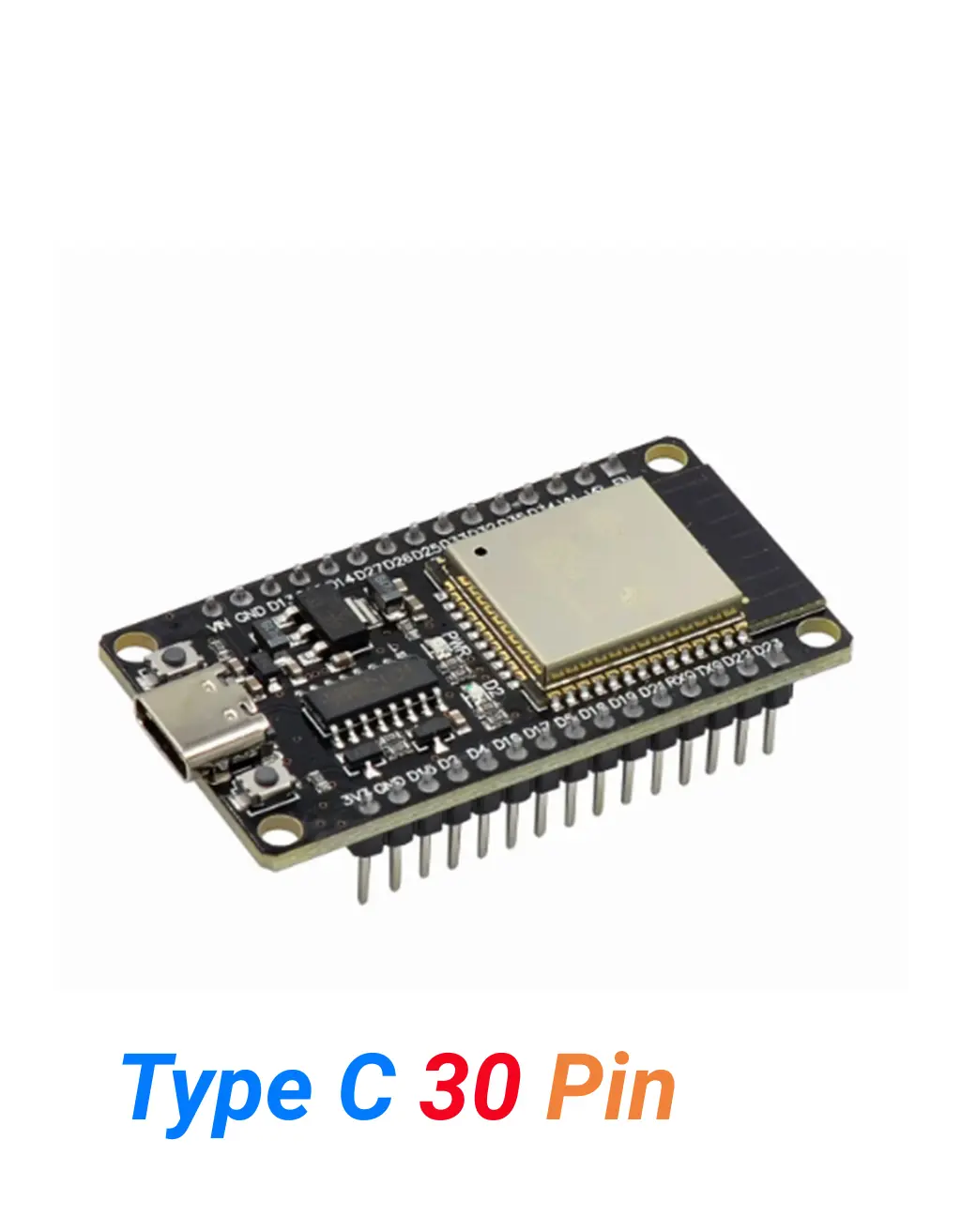
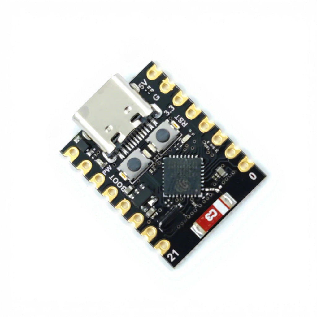
From your first blink project to advanced IoT systems — Dream RC stocks the hardware, writes the guides, and supports makers at every level across Bangladesh.
❓ Frequently Asked Questions
Common beginner questions about Arduino Uno and the blink LED project — answered for Bangladesh makers. 📋
🏁 Your First Step into the World of Electronics
You just completed your first Arduino project — blinking an LED. That might seem small, but it is genuinely significant. You installed software, selected the right board, wrote code, connected hardware, and made something physical respond to your instructions. That is the complete loop of embedded programming, and you have done it. 🎉
From here, every new project is just adding more pieces to the same foundation. A button is just another input. A sensor is just a smarter input. A motor driver is just a bigger output. WiFi is just a more powerful input/output layer — which is exactly where ESP32 comes in when you are ready.
Dream RC is here to support your journey — with tested hardware, practical guides written for Bangladesh beginners, and components available for nationwide delivery. From your first blink to your first robot to your first IoT system — we stock what you need and explain how to use it. 🇧🇩
📝 About This Guide: Written and maintained by the Dream RC team in Bangladesh. Last reviewed January 2026. All code examples tested on Arduino Uno R3 with Arduino IDE 2.3. Hardware specifications sourced from the official ATmega328P datasheet. If you spot an error or have a question, contact us via dream-rc.com. 🇧🇩