
Description
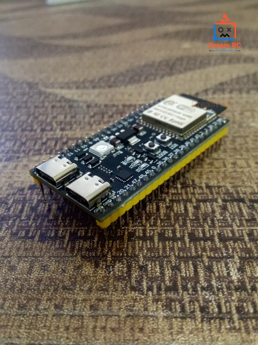
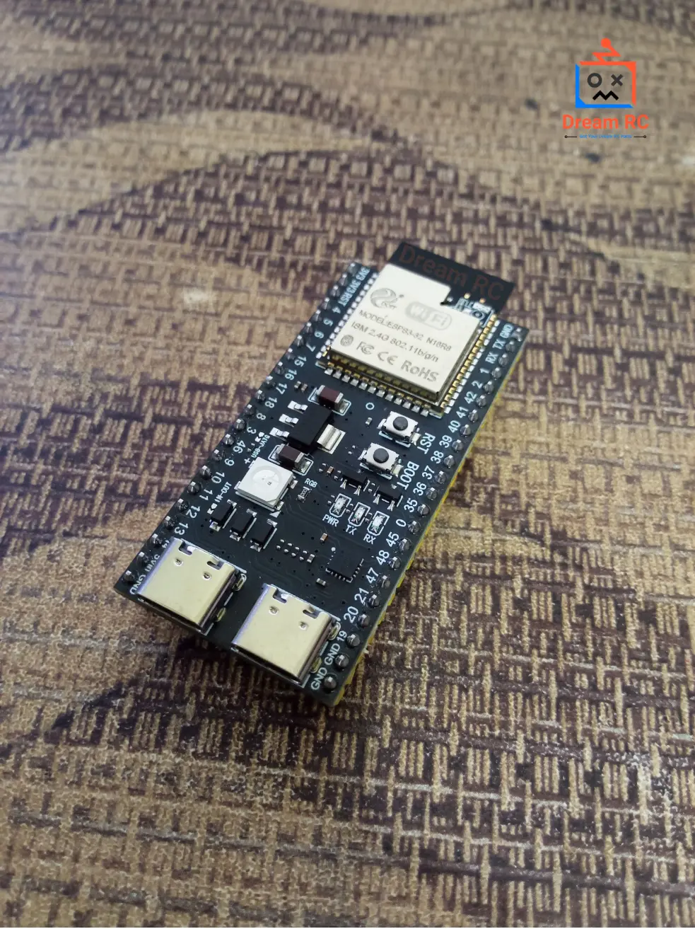
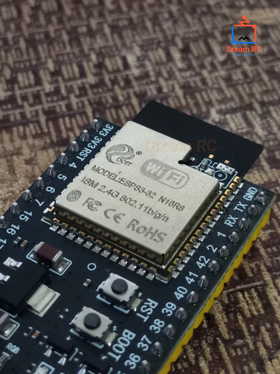
PRE-SOLDERED
TYPE-C + CP2102
AVAILABLE IN BANGLADESH
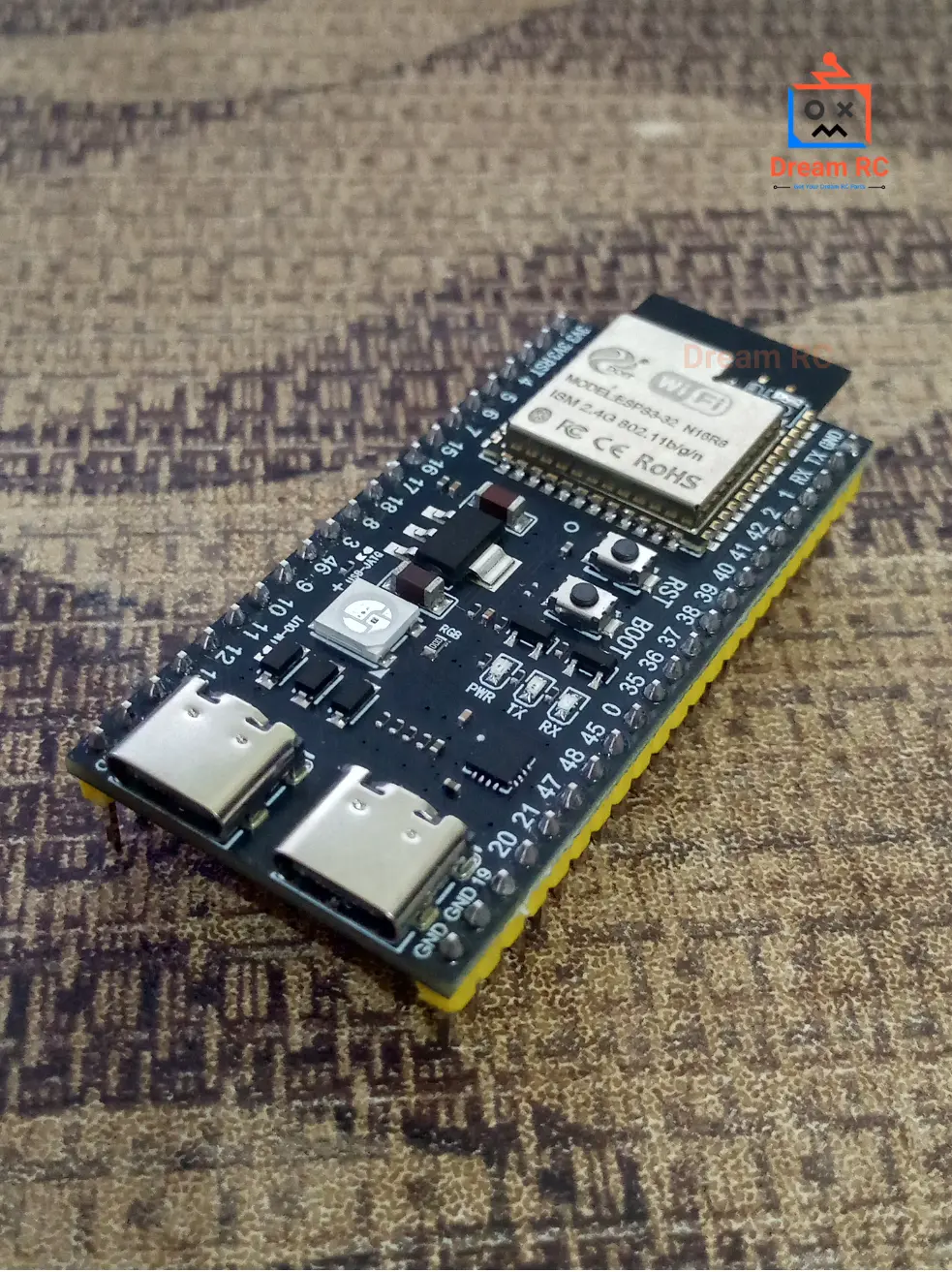
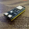
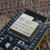
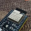
ESP32 S3 WROOM-1 N16R8
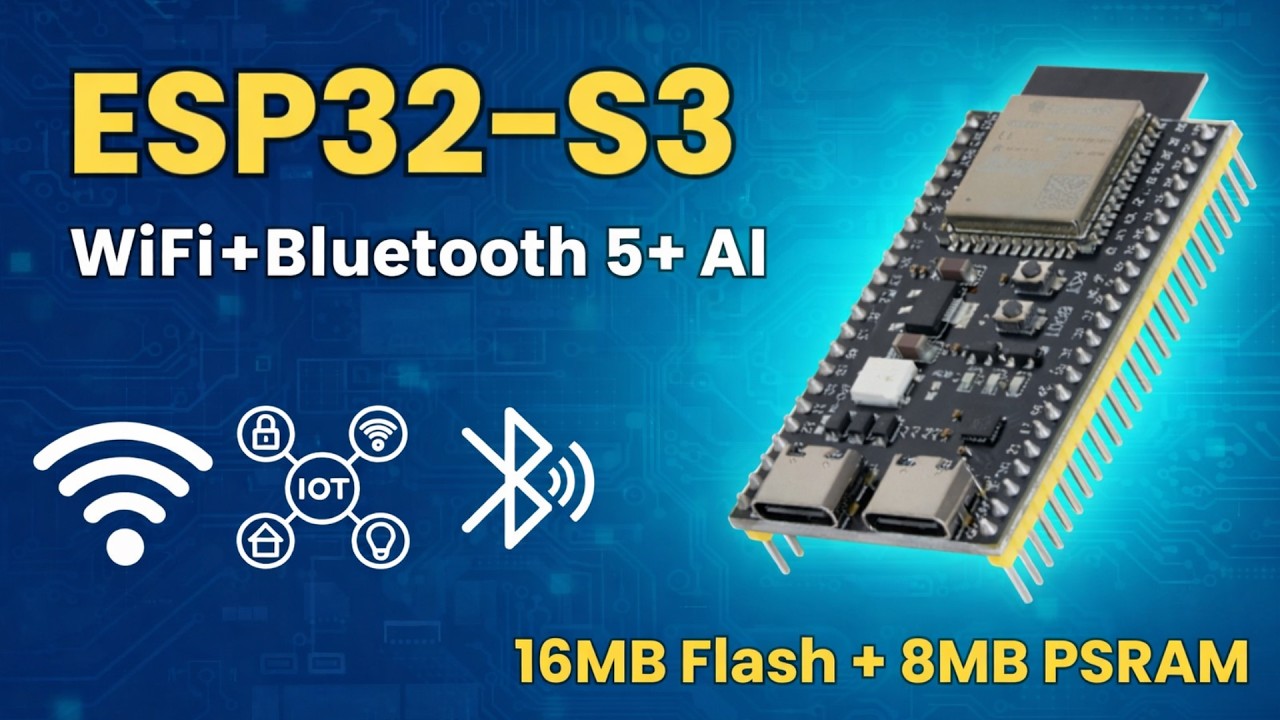
Espressif’s most powerful Wi-Fi + Bluetooth 5.0 development board — dual-core LX7 processor with hardware AI vector instructions, 16 MB flash, 8 MB OPI PSRAM at 80 MB/s. Built for AI, camera, edge-IoT, and Bluetooth 5.0 Long Range projects.
CPU
240MHz
Dual-core LX7
FLASH
16MB
NOR storage
PSRAM
8MB
OPI ~80 MB/s
WIRELESS
WiFi+
BT 5.0
Long Range
SLEEP
8µA
Deep sleep
GPIO
45
Programmable
The ESP32-S3 WROOM-1 N16R8 is Espressif’s highest-tier Wi-Fi and Bluetooth 5.0 module — combining a dual-core Xtensa LX7 processor at 240 MHz, a hardware 128-bit SIMD vector unit for AI acceleration, 16 MB of flash, and 8 MB of OPI PSRAM running at 80 MB/s. This is the only ESP32 module capable of real-time AI inference, smooth camera streaming, large OTA firmware updates, and Bluetooth 5.0 Long Range — all at the same time.
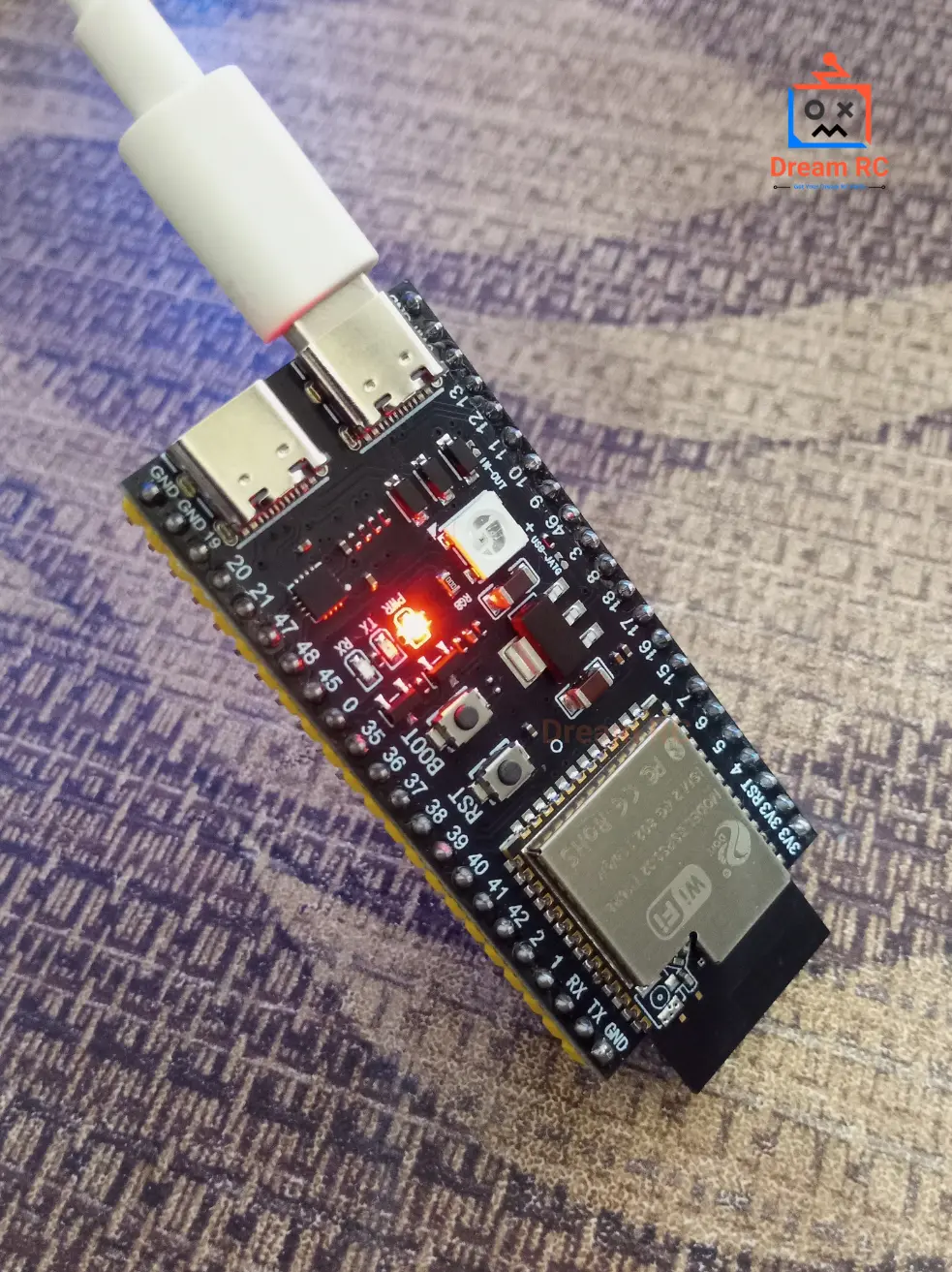
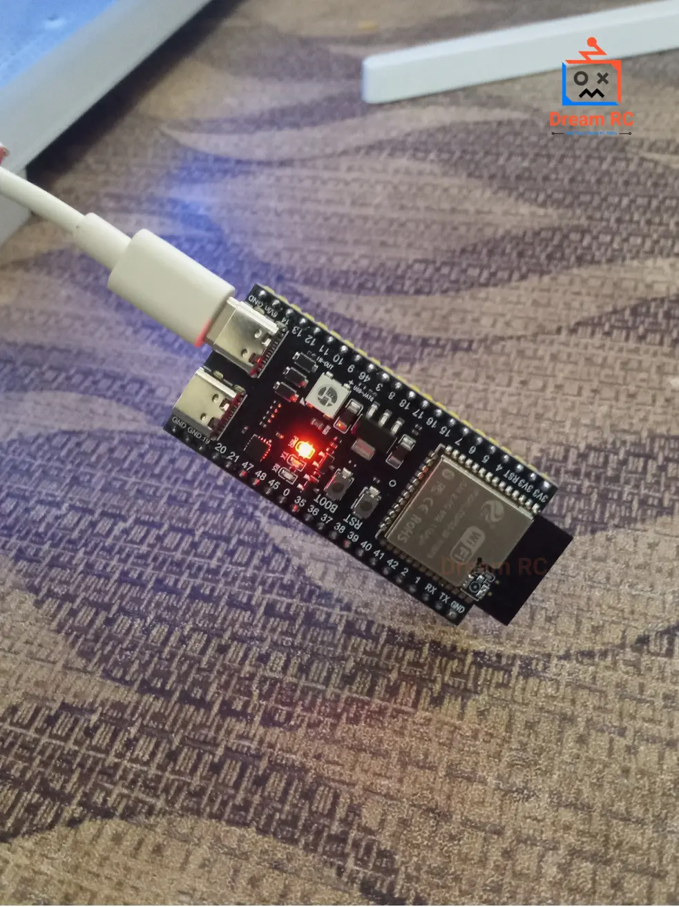
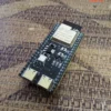
This unit ships with a CP2102 USB-to-Serial chip, Type-C USB port, and fully pre-soldered pin headers — plug in and start coding immediately. This complete product description covers everything about the ESP32-S3 N16R8: what N16R8 means, processor benchmarks, PSRAM advantages, full pinout with reliability guide, power consumption, security features, all peripherals, LED behavior, code examples with free downloads, troubleshooting, and the best price in Bangladesh.
🎬 ESP32-S3 N16R8 — Watch Before You Build
Watch this complete overview of the ESP32-S3 WROOM-1 N16R8 — specs explained, pinout walkthrough, Arduino IDE setup, and a live code demo.
This is the complete product guide and technical description for the ESP32-S3 WROOM-1 N16R8 development board available in Bangladesh from Dream RC at 839 BDT. This page covers N16R8 specifications, dual-core LX7 processor details, 16MB Flash and 8MB OPI PSRAM explained, WiFi and Bluetooth 5.0 range data, full pinout guide, LED behaviour, CH340/CP2102 driver setup, Arduino IDE configuration, downloadable code examples, AI and TinyML capabilities, IPEX antenna port guide, and troubleshooting. Whether you are searching for ESP32-S3 N16R8 price in Bangladesh, a complete getting-started guide, or technical specs — this page has everything.
📑 Table of Contents — ESP32-S3 WROOM-1 N16R8
This complete guide covers everything about the ESP32-S3 WROOM-1 N16R8 development board — from the meaning of N16R8 and processor benchmarks to pinout, power, security, code examples, and where to buy it at the best price in Bangladesh.
- Quick Specs at a Glance
- Official Datasheet & Resources
- What N16R8 Means
- N16R8 vs N8R8 vs N8R2
- LX7 vs ESP32 LX6 Processor
- Key Features
- Deep Dive: Dual-Core LX7
- AI / ML Capability
- Native USB Explained
- WiFi & BLE Range (Real Data)
- PSRAM Advantage
- Power, Sleep & Current Draw
- Security Features
- Peripherals Overview
- Pinout + Color Legend
- Pin Reliability Guide
- Board Schematic
- Onboard LED Behavior
- Boot & Reset Buttons
- What You Can Build
- Who Should Buy This?
- ESP32-S3 vs ESP32 vs ESP8266
- Full Specifications Table
- CP2102 Driver Install
- Arduino IDE Settings
- Code Examples + Free Downloads
- ESP-NOW & Mesh Networking
- Troubleshooting
- FAQ + Schema
- Price in BD & Why Dream RC
⚡ Quick Specs at a Glance
240MHz
DUAL-CORE LX7
16MB
FLASH STORAGE
8MB
OPI PSRAM
512KB
INTERNAL SRAM
45
GPIO PINS
BT 5.0
LONG RANGE
+20dBm
TX POWER
8µA
DEEP SLEEP
📚 Official Datasheet & Resources
Always use official Espressif documentation for accurate specs. Every link below is the primary source — bookmark these before starting your project.
📄 WROOM-1 Module Datasheet
Official module specs — pinout, RF, antenna, dimensions
📄 ESP32-S3 SoC Datasheet
Full chip datasheet — peripherals, registers, power modes
📘 Technical Reference Manual
1000+ pages — deep reference for firmware developers
⚡ ESP-IDF API Reference
Complete C/C++ API docs for ESP32-S3
⚡ Arduino-ESP32 GitHub
Official Arduino board package — install via Boards Manager
🔌 CP2102 Driver (Silicon Labs)
Required USB driver — Windows / Mac / Linux
🤖 ESP-DL AI Library
Espressif deep-learning library optimized for LX7
👁️ ESP-WHO (Face Detection)
Camera AI library — person detect, face recognition
🔤 What Does “N16R8” Actually Mean?
The suffix on Espressif’s part numbers tells you exactly how much memory is inside the module.
Here is the full decoder for ESP32-S3-WROOM-1 N16R8:
PART NUMBER DECODER
ESP32-S3-WROOM-1
N16
R8
N16
FLASH MEMORY
N = NOR Flash type |
16 = 16 Megabytes
Stores your sketch, OTA firmware, SPIFFS/LittleFS files
R8
OCTAL-SPI PSRAM
R = RAM (PSRAM) |
8 = 8 Megabytes
OPI = 8-bit bus @ 80 MHz = ~80 MB/s bandwidth
16 MB Flash + 8 MB Octal-SPI PSRAM.
This is the highest-tier WROOM-1 variant — used in the official
ESP32-S3-EYE AI camera kit and in production AI / camera products worldwide.
🥇 N16R8 vs N8R8 vs N8R2 — Real Data Comparison
Visual bandwidth bars + data table — see exactly where the cheaper variants fall short.
Flash Storage
N16R8
16 MB
N8R8
8 MB
N8R2
8 MB
PSRAM Bandwidth (Higher = Faster Camera & AI)
N16R8
~80 MB/s
N8R8
~80 MB/s
N8R2
~40 MB/s ⚠️
| Spec | BEST CHOICE N16R8 | MID RANGE N8R8 | BUDGET N8R2 |
|---|---|---|---|
| Flash | 16 MB | 8 MB | 8 MB |
| PSRAM | 8 MB OPI | 8 MB OPI | 2 MB QSPI |
| PSRAM Bus Width | 8-bit OPI | 8-bit OPI | 4-bit QSPI |
| PSRAM Bandwidth | ~80 MB/s | ~80 MB/s | ~40 MB/s ⚠️ |
| Camera 640×480 frames | ✅ 3+ frames | ✅ 3+ frames | ⚠️ 1 frame only |
| TF-Lite person detect | ~10 FPS | ~10 FPS | ~5 FPS |
| OTA + big sketch room | ✅ 3MB+3MB+10MB | ⚠️ Limited | ⚠️ Limited |
⚡ Processor Showdown — LX7 vs Original ESP32 LX6
| Benchmark / Feature | ESP32-S3 LX7 | ESP32 LX6 |
|---|---|---|
| CoreMark (dual-core) | ~1181 pts | ~994 pts |
| 128-bit SIMD Vector Unit | ✅ Yes | ❌ No |
| INT8 Matrix Multiply speed | ~16× faster | Baseline |
| Person detect @ 96×96 INT8 | ~10 FPS | ~1 FPS |
| Native USB OTG | ✅ Built-in | ❌ External chip |
| Bluetooth | 5.0 LE + Long Range | 4.2 + BLE |
| GPIOs | 45 | 34 |
| Touch Channels | 14 | 10 |
⭐ Key Features
Dual-Core LX7 @ 240MHz
~19% faster than LX6 + 128-bit SIMD for AI
16MB Flash + 8MB OPI PSRAM
80 MB/s bandwidth for AI, camera, OTA
Native USB OTG + Type-C
HID keyboard/mouse, MSC, CDC — no extra chip
AI / ML Acceleration
Vector ISA — TF-Lite up to 16× faster than LX6
Wi-Fi 4 + Bluetooth 5.0 LE
2.4 GHz + BLE Long Range up to ~400 m
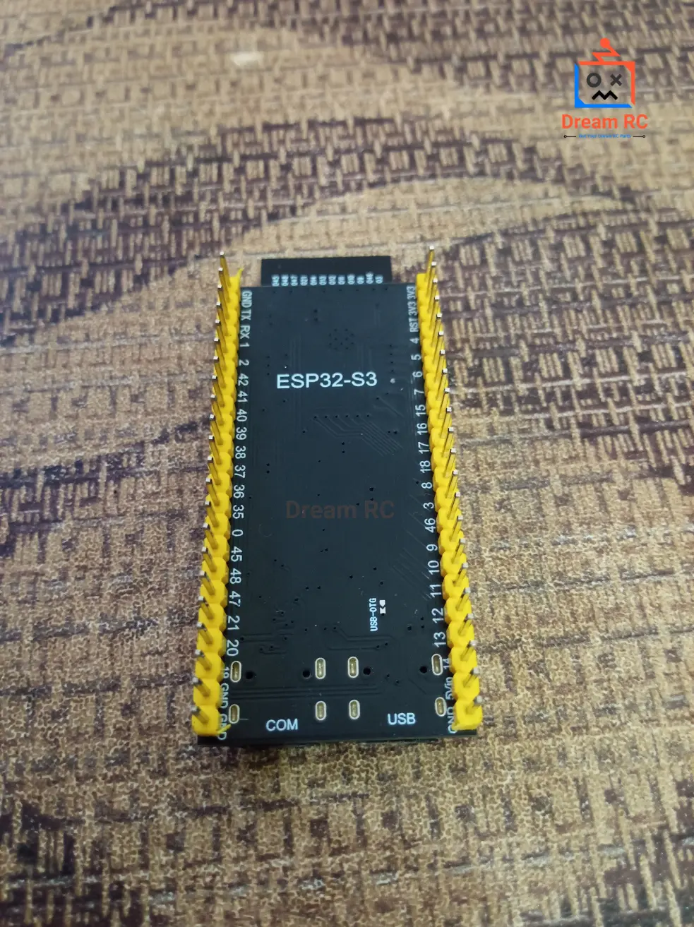
45 GPIOs + Pre-Soldered
Headers already welded — plug in and go
Hardware Security
Secure Boot V2 + AES-XTS-256 Flash Encryption
Ultra-Low Power Sleep
8 µA deep sleep, ULP coprocessor active at 24 µA
IPEX / u.FL Antenna Port
External antenna connector onboard — connect a 2.4GHz high-gain antenna to extend WiFi range to 600m+
🧠 Deep Dive — Dual-Core Xtensa LX7 Processor
The ESP32-S3 runs two Xtensa LX7 32-bit cores at up to 240 MHz. At the same clock speed as the original ESP32’s LX6, the LX7 delivers better performance through a redesigned pipeline, higher instruction-level parallelism, and most importantly a completely new 128-bit SIMD vector unit — hardware that simply does not exist on any other ESP32.
🔀 True Dual-Core FreeRTOS
Run Wi-Fi/BLE on Core 0 and your application on Core 1 simultaneously — no timesharing, true parallelism.
📊 128-bit SIMD Vector Unit
Processes 16 INT8 values in a single clock cycle — the engine that makes edge AI practical.
💡 RISC-V ULP Coprocessor
Wakes at 24 µA to poll sensors in deep sleep — main cores stay off until needed.
🗃️ 8.5 MB Total Usable RAM
512 KB on-chip SRAM + 8 MB external PSRAM = ~8.5 MB available to your code.
xTaskCreatePinnedToCore() to pin your critical loop to Core 1 and let Core 0 handle all wireless. This alone can double effective throughput in sensor + networking projects.🤖 Deep Dive — AI & Machine Learning at the Edge
The ESP32-S3 was specifically engineered for edge AI. Its vector instructions turn what used to take 10 seconds (on the original ESP32) into a sub-100ms real-time result. Here are real use-cases running fully on-device — no cloud, no internet required:
🗣️
Voice Wake-Word (ESP-SR)
“Hey Marvin”-style local wake-word detection. No cloud. Latency <100 ms.
👁️
Person / Object Detection
~10 FPS at 96×96 INT8 with TF-Lite Micro on Core 1 while Core 0 handles Wi-Fi.
😀
Face Detection & Recognition
ESP-WHO library — 5–10 FPS face detect with recognition on-device.
🌱
TinyML — Edge Impulse
Train anomaly detection / gesture models in Edge Impulse, deploy to S3 in one click.
🔊
Audio Classification
Classify sounds (glass break, cough, machine noise) locally at <50 ms.
🛡️
Privacy-First AI
All inference on-device — no audio or video ever leaves the hardware.
RECOMMENDED AI LIBRARIES FOR ESP32-S3
ESP-WHO
ESP-SR
TensorFlow Lite Micro
Edge Impulse
MicroPython ulab
🔌 Deep Dive — Native USB OTG (HID, Keyboard, Mouse, Mass Storage)
A standout feature of the ESP32-S3 is built-in USB 1.1 Full-Speed OTG on GPIO 19 (D−) and GPIO 20 (D+). The original ESP32 needs an external CP2102/CH340 chip for every USB action — the S3 has it built directly into silicon, opening four USB classes that were impossible before:
⌨️ USB HID — Keyboard / Mouse
Board appears as a real keyboard or mouse to any PC/Mac. Build macro pads, stream decks, accessibility tools, gaming controllers.
💿 USB CDC — Serial Programming
Upload sketches and see Serial Monitor over native USB — no CP2102 chip needed at all if you use GPIO 19/20 directly.
💾 USB MSC — Mass Storage
Board appears as a USB flash drive — users drag-drop files without any custom driver.
🎮 USB Host — Connect Devices
Plug a USB keyboard, mouse, or game controller into the S3 and read it as a host device.
📡 Deep Dive — Wi-Fi + Bluetooth 5.0 Range (Real-World Numbers)
“Supports Wi-Fi and Bluetooth” means nothing without real numbers. Here is what to actually expect from the WROOM-1 PCB antenna in real conditions, and exactly how to maximize your range.
📶 Wi-Fi 2.4 GHz (802.11 b/g/n)
📡 Bluetooth 5.0 LE
🚀 How to Maximize Your Range
- Set maximum TX power:
WiFi.setTxPower(WIFI_POWER_19_5dBm); - Switch to WROOM-1U variant (external IPEX antenna) for 2–3× more range
- For BLE: use Long Range Coded PHY S=8 — 4× the range of standard BLE 4.2
- Mount board high, keep away from metal surfaces, water pipes and USB 3.0 cables
- For point-to-point >1 km: use directional antenna (Yagi) + external amplifier
💾 Deep Dive — Why 8 MB OPI PSRAM Is a Game Changer
The ESP32-S3 SoC has only 512 KB of internal SRAM — barely enough for the Wi-Fi stack and a small program. PSRAM is the extra workspace. The N16R8 uses the fastest tier: 8 MB Octal-SPI PSRAM at 80 MHz — 8 data lines delivering ~80 MB/s, exactly twice the QSPI variant in N8R2.
📷 Camera Frame Buffers
A 640×480 RGB565 frame = 614 KB. With 8 MB PSRAM you hold 3+ frames for double-buffered JPEG encoding at full speed.
🤖 AI Model Weights
MobileNet-V1 INT8 ≈ 2–3 MB. Without PSRAM these models simply cannot load. 8 MB fits most practical TinyML models.
🔊 Audio Buffers
16 kHz 16-bit mono = 32 KB/s. 8 MB PSRAM can buffer ~4 minutes of audio for wake-word and speech processing.
🌐 Web / LVGL UI Caches
Large HTML/JSON responses and full LVGL color frame-buffers for TFT screens without fragmenting the heap.
🔋 Power Consumption & Sleep Modes
The ESP32-S3 has five power states. Understanding them is essential for battery-powered projects. All figures are for the SoC alone at 3.3 V — your dev board adds ~5–10 mA for the LDO, LEDs, and CP2102.
| Power Mode | Current Draw | What is Active |
|---|---|---|
| Active (Wi-Fi TX) | ~310 mA peak | Both cores + Wi-Fi transmitting at max power |
| Active (CPU only) | ~80–100 mA | Both cores at 240 MHz, Wi-Fi/BLE radio off |
| Modem-Sleep | ~20–30 mA | CPU active, radio sleeps between beacons — good for connected IoT sensors |
| Light Sleep | ~1–2 mA | CPU paused, RAM retained, wakes on timer/GPIO/UART |
| Deep Sleep (ULP off) | ~8 µA | Only RTC memory + RTC GPIO + wakeup timers. Main RAM lost. |
| Deep Sleep (ULP active) | ~24 µA | RISC-V ULP coprocessor runs — polls sensors while main cores sleep |
esp_deep_sleep_start() in ESP-IDF or ESP.deepSleep() in Arduino.🛡️ Hardware Security Features
The ESP32-S3 is one of the few microcontrollers at this price point with hardware-enforced security. This makes it suitable for production commercial products where firmware protection and secure communication matter.
🔐 Secure Boot V2
Only firmware signed with your private RSA-3072 key will run. Prevents unauthorized firmware from booting.
🔒 Flash Encryption (AES-XTS-256)
All flash contents encrypted at rest. Reading the flash chip directly reveals only ciphertext — your firmware and keys stay secret.
🔑 eFuse OTP Memory
One-time-programmable fuses store root keys, device IDs and security flags permanently — cannot be overwritten.
🧮 Hardware Crypto Engines
AES-128/256, SHA-256/512, RSA, ECC, and True RNG — all accelerated in hardware. TLS/HTTPS at full speed.
🛑 Digital Signature Block
Private key stored in hardware — software can request signatures without ever exposing the raw key bytes.
🔥 HMAC-Based Secure OTA
OTA firmware updates verified by hardware HMAC — prevents downgrade attacks and firmware tampering.
🔩 Peripherals Overview
The ESP32-S3 packs an extensive peripheral set. All interfaces are routed through a GPIO matrix — meaning almost any peripheral can be mapped to almost any pin.
🔢
ADC
2× 12-bit SAR, 20 channels
👆
Touch Sensor
14 capacitive channels
🔁
UART
3× hardware UART
🔗
SPI
4× SPI (2 general)
🔗
I²C
2× I²C (master + slave)
🎵
I²S Audio
2× I²S (mic + speaker)
🌈
LEDC PWM
8 channels, any GPIO
📷
Camera (DVP)
8–16 bit parallel camera
🖥️
LCD (8/16-bit)
Parallel LCD controller
⏱️
Timers
4× 54-bit general timers
📡
RMT (IR/WS2812)
8 channels — IR remote, NeoPixel
🔄
MCPWM
Motor control PWM — servos, BLDC
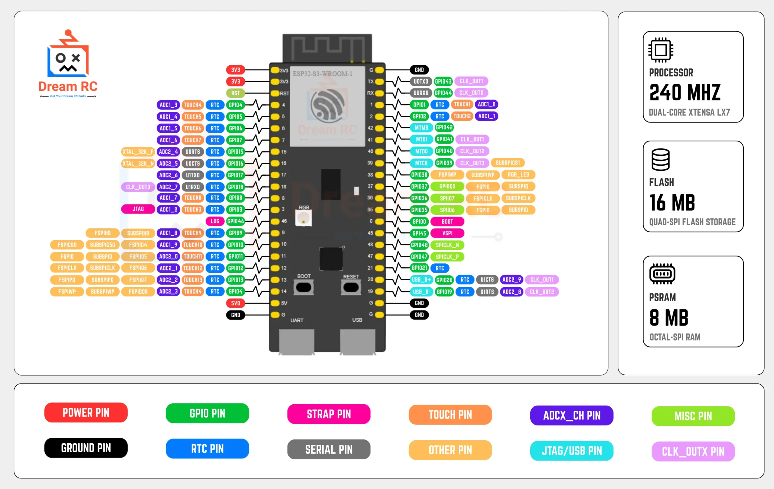
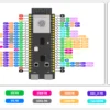
📍 Pinout Diagram + Color Legend

The ESP32-S3 WROOM-1 N16R8 exposes 45 programmable GPIOs but they are not all equal. Use this color legend alongside the pinout image above to instantly know which pins are safe for your project:
RED — Power Pins
3V3, 5V (VIN). Source pins — never short to GND.
BLACK — Ground (GND)
Common reference for all signals and power.
GREEN — Safe General GPIO
Use freely for I/O, PWM, I2C, SPI, UART.
BLUE — ADC / Touch
GPIO 1–10 (ADC1 — works with Wi-Fi). Also 14 touch channels.
YELLOW — Strapping Pins
GPIO 0, 3, 45, 46. State at boot affects boot mode — use carefully.
PURPLE — Native USB OTG
GPIO 19 (D−) and GPIO 20 (D+). Avoid for general I/O if using native USB.
PINK — Reserved / Internal
GPIO 26–32 (Flash), 33–37 (PSRAM). Never connect anything to these.
TEAL — ARGB LED
GPIO 48 (some boards GPIO 38). WS2812 onboard ARGB LED.
🎯 Pin Reliability Guide — What to Use & What to Avoid
| Category | GPIO Pins | Guidance |
|---|---|---|
| ✅ Best for beginners | GPIO 4, 5, 6, 7, 15, 16, 17, 18, 21 | Safe for everything: button, LED, PWM, I2C, SPI, UART. No conflicts. |
| 🔵 ADC1 (safe with Wi-Fi) | GPIO 1–10 | Analog reads work reliably even when Wi-Fi is active. Always use ADC1 for analog. |
| ⚠️ ADC2 (Wi-Fi conflict) | GPIO 11–20 | ADC reads silently fail when Wi-Fi is on. Fine for digital I/O — avoid for analog. |
| ⚠️ Strapping pins | GPIO 0, 3, 45, 46 | Don’t pull GPIO 0 HIGH at boot (forces download mode). Use only as outputs after boot. |
| 🟣 Native USB OTG | GPIO 19, 20 | Leave free if you use native USB (HID/MSC). Safe for other I/O if not using USB OTG. |
| ⛔ Reserved — DO NOT USE | GPIO 26–37 | Connected to internal Flash and OPI PSRAM. Touching these will crash or brick the board. |
| ✅ Reliable PWM | GPIO 4–18, 21 (best) | All GPIOs support LEDC PWM. GPIO 4–18 are most reliable for servo, dimmer, buzzer. |
| ✅ ARGB LED control | GPIO 48 (GPIO 38 on some boards) | Use Adafruit_NeoPixel or FastLED. Try GPIO 38 if 48 does not work. |
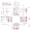
🛠️ Board Schematic
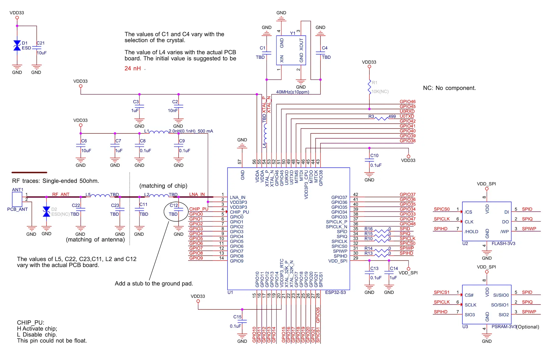
The schematic shows the full board wiring. Key areas to understand:
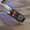
- 5V Type-C input → AMS1117-3.3 LDO → 3.3V rail powering the WROOM-1 module
- CP2102 RX/TX connected to GPIO 43 (U0TXD) and GPIO 44 (U0RXD)
- Auto-reset circuit — DTR/RTS from CP2102 toggle EN + GPIO 0 for automatic download mode
- BOOT button — pulls GPIO 0 to GND to enter download mode manually
- RESET button — pulls EN (chip enable) to GND to reset the chip
- ARGB WS2812 LED on GPIO 48 (single-wire data protocol)
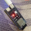
- Red power LED connected to the 3.3V rail via resistor
💡 Onboard LED Behavior — What Every Blink Means
Three LEDs are on this board. Knowing what each pattern means saves hours of debugging.
🔘 Boot & Reset Buttons — What They Do
⚫ BOOT Button (GPIO 0)
- Normal use: Does nothing during normal operation — GPIO 0 is just a GPIO when the board is running.
- During upload: Hold BOOT while pressing RESET (or while connecting USB) — this puts the board into download mode so Arduino IDE / esptool can flash firmware.
- Auto-reset: The CP2102 auto-reset circuit does this automatically on most uploads — you only need to press BOOT manually if auto-reset fails.
🔄 RESET Button (EN Pin)
- Press once: Reboots the chip and restarts your sketch from the beginning — like power cycling.
- With BOOT held: Press RESET while holding BOOT → release RESET → release BOOT = enters download mode manually.
- After upload: If the board does not auto-reboot after upload, press RESET once to start the new sketch.
🚀 What You Can Build — Real Projects for ESP32-S3 N16R8
These are real projects that specifically benefit from the LX7 vector unit, 8 MB PSRAM, native USB, and BLE 5.0 — things the original ESP32 either cannot do or does far too slowly.
👤 Who Should Buy This?
🎓 Beginners
Pre-soldered headers — zero soldering needed. Plug into breadboard and start with Arduino IDE in under 10 minutes.
📚 Students
Perfect for university projects in IoT, AI, embedded systems, wireless comms and final-year research.
⚙️ Engineers
Maximum Flash, PSRAM bandwidth, and hardware security for production commercial IoT and AI products.
🛠️ Hobbyists & Makers
Smart home, wearables, BLE gadgets, AI edge devices, WLED displays, custom keyboards and more.
⚔️ ESP32-S3 vs ESP32 vs ESP8266 — Full Comparison
Side-by-side comparison to help you pick the right board for your project.
| Feature | RECOMMENDED ESP32-S3 WROOM-1 N16R8 | POPULAR ESP32 Classic Dev Board | BUDGET ESP8266 NodeMCU / D1 Mini |
|---|---|---|---|
| CPU Core | Dual LX7 240MHz | Dual LX6 240MHz | Single 80–160MHz |
| AI Vector Unit | ✅ 128-bit SIMD | ❌ None | ❌ None |
| Flash Memory | 16 MB | 4 MB typical | 4 MB |
| PSRAM | 8 MB OPI | None / 4MB QSPI | ❌ None |
| Bluetooth | BT 5.0 LE + LR | BT 4.2 + BLE | ❌ No BT |
| Native USB OTG | ✅ HID + MSC + CDC | ❌ No | ❌ No |
| Hardware Security | ✅ Secure Boot + AES-256 | Basic | ❌ None |
| USB Connector | Type-C + CP2102 | Micro USB | Micro USB |
| GPIO Pins | 45 | 34 | 17 |
| Deep Sleep | 8 µA | 10 µA | 20 µA |
| Pre-Soldered (Dream RC) | ✅ Yes — ready to use | Varies by seller | Varies by seller |
🔧 Full Features & Specifications
🔧 CP2102 Driver — Download & Install Guide
Your PC needs the CP2102 USB-to-Serial driver to detect the board. Without it no COM port will appear and you cannot upload any code.
Download CP2102 Driver (Official Silicon Labs)
Download the CP210x Universal Windows Driver directly from Silicon Labs — always use the official source.
Extract & Run the Installer
Extract the ZIP → run CP210xVCPInstaller_x64.exe (64-bit Windows) or x86 for 32-bit → Next → Install → Done.
Verify the COM Port Appears
Plug Type-C cable → open Device Manager → expand Ports (COM & LPT) → look for Silicon Labs CP210x USB to UART Bridge (COM X).
Install ESP32 Board Package in Arduino IDE
File → Preferences → paste this in Additional Boards Manager URLs:
https://raw.githubusercontent.com/espressif/arduino-esp32/gh-pages/package_esp32_index.json
Then Tools → Board → Boards Manager → search esp32 → install esp32 by Espressif Systems v2.0.0+.
⚙️ Arduino IDE Settings — Exact Values for N16R8
Wrong settings are the #1 cause of upload failures, blank Serial Monitor, and Wi-Fi issues. Use these exact values every time:
💡 BLE Tip: ESP32 board package v2.0.0+ is required for full Bluetooth 5.0 Long Range support on the S3.
💻 Code Examples — Copy-Paste + Free .ino Downloads
Four ready-to-upload Arduino sketches. Each has a Download .ino button that saves the file directly to your computer.
📡 ESP-NOW & Mesh Networking
ESP-NOW is Espressif’s proprietary peer-to-peer wireless protocol that lets multiple ESP32-S3 boards talk to each other without any router or Wi-Fi network. It’s ideal for sensor networks, remote controls, and mesh systems.
⚡ Ultra-Low Latency
~1 ms delivery time vs ~100 ms for standard Wi-Fi. Perfect for real-time control.
🔋 No Router Needed
Boards communicate directly — great for remote or off-grid deployments.
🌐 Up to 20 Peers
One board can communicate with up to 20 others simultaneously.
🕸️ Mesh with ESP-Mesh
Scale to hundreds of nodes using Espressif’s ESP-WIFI-MESH protocol.
🩺 Troubleshooting — Common Issues & Fixes
❓ Frequently Asked Questions
📚 Learn More — ESP32-S3 Guides & Project Tutorials
Bought your ESP32-S3 N16R8 and ready to start building? These Dream RC guides take you from first setup all the way to advanced AI, camera, and Bluetooth 5.0 Long Range projects:
📦 Package Includes
📦
1 × ESP32-S3 WROOM-1 N16R8 Development Board
Pre-soldered (welded) pin headers included. USB cable and accessories not included.
💬 ESP32-S3 N16R8 Price in BD & Why Buy From Dream RC?
The ESP32-S3 WROOM-1 N16R8 price in BD is 839 BDT. Buy from Dream RC — Bangladesh’s trusted source for development boards, IoT modules, and electronics components at the best price nationwide.
This board comes with pre-soldered headers, genuine CP2102 chip, Type-C USB, 16 MB flash, and 8 MB OPI PSRAM — ready to use out of the box. Order with confidence — Cash on Delivery available everywhere in Bangladesh.
✅ COD Available
Pay after receiving
⚡ Fast Dispatch
Quick processing time
🚚 Inside Dhaka
69 BDT — within 24 hrs
🛵 Outside Dhaka
129 BDT — 24 to 72 hrs
sultanularafin8 –
ESP32 S3 N16R8 বোর্ডটি খুবই Powerful এবং stable। Wi-Fi ও Bluetooth ভালো কাজ করে, আর 16MB Flash + 8MB PSRAM থাকায় বড় প্রজেক্টেও সমস্যা হয় না। Arduino IDE দিয়ে সহজে প্রোগ্রাম করা যায়। দামের তুলনায় খুব ভালো একটি বোর্ড। Highly recommended!