

Description
PRE-SOLDERED
TYPE-C + CH340
AVAILABLE IN BANGLADESH
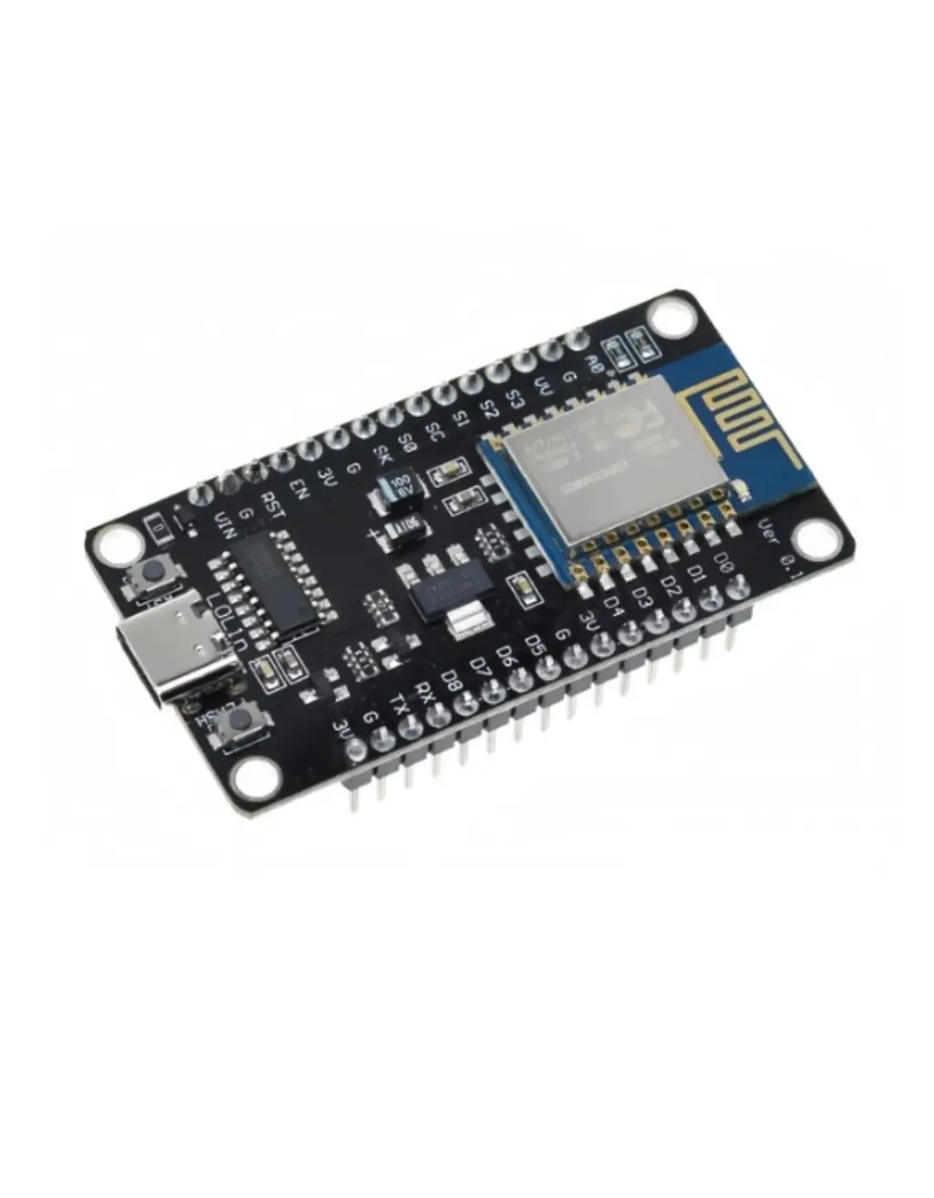
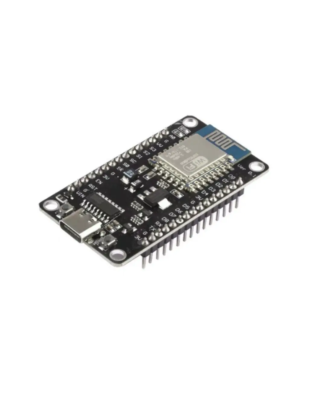
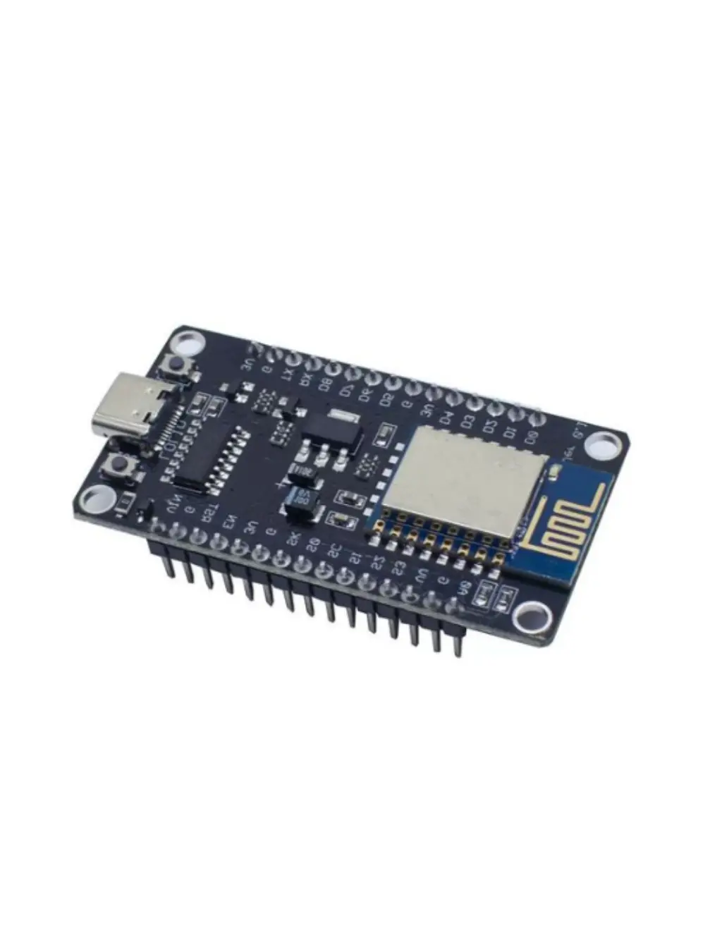
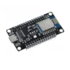
ESP8266 NodeMCU V3 (Type-C)
The world’s most popular WiFi development board — Tensilica L106 processor at 80/160 MHz, 4 MB flash, built-in WiFi 802.11 b/g/n, modern USB Type-C connector with CH340C chip. The perfect starting point for IoT, home automation, and WiFi projects.
CPU
160MHz
Tensilica L106
FLASH
4MB
SPI Flash
RAM
160KB
SRAM (~50 KB free)
WIRELESS
WiFi
b/g/n
2.4 GHz
SLEEP
20µA
Deep sleep
GPIO
17
Programmable
The ESP8266 NodeMCU V3 (Type-C) is the world’s most popular WiFi development board — trusted by millions of makers, students, and engineers for IoT projects since 2014. Built around the ESP8266EX SoC with a Tensilica L106 32-bit RISC processor running at up to 160 MHz, 4 MB of SPI flash, and a full 802.11 b/g/n WiFi stack, this board connects your projects to the internet for under 400 BDT.
This upgraded Type-C version features a USB Type-C connector for reversible plug-in, a reliable CH340C USB-to-Serial chip, and fully pre-soldered pin headers — plug in and start coding immediately. This complete product description covers everything about the ESP8266 NodeMCU: processor specs, WiFi range, full pinout guide, power consumption, all peripherals, LED behavior, code examples with free downloads, troubleshooting, and the best price in Bangladesh.
🎬 ESP8266 NodeMCU — Watch Before You Build
Watch this complete overview of the ESP8266 NodeMCU V3 Type-C — specs explained, pinout walkthrough, Arduino IDE setup, and a live WiFi demo.
This is the complete product guide and technical description for the ESP8266 NodeMCU V3 Type-C development board available in Bangladesh from Dream RC at 325 BDT. This page covers ESP8266 specifications, Tensilica L106 processor details, 4MB Flash explained, WiFi 802.11 b/g/n range data, full pinout guide, LED behaviour, CH340 driver setup, Arduino IDE configuration, downloadable code examples, power consumption and deep sleep, and troubleshooting. Whether you are searching for ESP8266 NodeMCU price in Bangladesh, a complete getting-started guide, or technical specs — this page has everything.
📑 Table of Contents — ESP8266 NodeMCU V3 Type-C
This complete guide covers everything about the ESP8266 NodeMCU V3 Type-C development board — from processor specs and WiFi range to pinout, power, code examples, and where to buy it at the best price in Bangladesh.
- Quick Specs at a Glance
- Official Datasheet & Resources
- What is NodeMCU?
- V3 Type-C vs V2 vs V1
- Tensilica L106 Processor
- Key Features
- WiFi Deep Dive (Real Data)
- Power, Sleep & Current Draw
- Peripherals Overview
- Pinout + Color Legend
- Pin Reliability Guide
- Board Schematic
- Onboard LED Behavior
- Flash & Reset Buttons
- What You Can Build
- Who Should Buy This?
- ESP8266 vs ESP32 vs ESP32-S3
- Full Specifications Table
- CH340 Driver Install
- Arduino IDE Settings
- Code Examples + Free Downloads
- Troubleshooting
- FAQ + Schema
- Price in BD & Why Dream RC
⚡ Quick Specs at a Glance
160MHz
TENSILICA L106
4MB
FLASH STORAGE
160KB
SRAM
17
GPIO PINS
WiFi
802.11 b/g/n
+20dBm
TX POWER
20µA
DEEP SLEEP
325
BDT PRICE
📚 Official Datasheet & Resources
Always use official Espressif documentation for accurate specs. Every link below is the primary source — bookmark these before starting your project.
📄 ESP8266EX Datasheet
Official SoC specs — pinout, RF, power, peripherals
📘 Technical Reference Manual
Deep reference for registers, peripherals, memory map
⚡ ESP8266 RTOS SDK
Official FreeRTOS-based SDK for advanced development
⚡ Arduino-ESP8266 GitHub
Official Arduino board package — install via Boards Manager
🔌 CH340 Driver (WCH Official)
Required USB driver — Windows / Mac / Linux
📝 NodeMCU Lua Documentation
Official Lua firmware docs — alternative to Arduino IDE
🕄 What is “NodeMCU” — Name Explained
The name “NodeMCU” originally referred to the Lua-based firmware for the ESP8266 chip. Over time, it became the name of the entire development board ecosystem. Here is the full breakdown:
NAME DECODER
NodeMCU
V3
Type-C
Node
IoT NODE
Each board is a “node” in your IoT network — connects to WiFi and communicates with other devices
MCU
MICROCONTROLLER
ESP8266EX chip = full microcontroller with CPU, RAM, Flash, WiFi radio all in one
V3-C
VERSION + USB
V3 = latest revision with CH340 chip. Type-C = modern reversible USB connector
🥇 V3 Type-C vs V2 vs V1 — Which NodeMCU Version?
Visual comparison + data table — see exactly why V3 Type-C is the best choice today.
| Spec | BEST CHOICE V3 Type-C | PREVIOUS V2 (Amica) | LEGACY V1 (Devkit) |
|---|---|---|---|
| USB Connector | Type-C (Reversible) | Micro-USB | Micro-USB |
| USB-Serial Chip | CH340C | CP2102 | CH340G |
| Board Width | ~25mm (Wide) | ~24mm (Narrow) | ~31mm (Very Wide) |
| Breadboard Friendly | ✅ Yes (1 row each side) | ✅ Best fit | ⚠️ Covers full board |
| Flash Size | 4 MB | 4 MB | 4 MB |
| Pin Labels | ✅ Clear D0-D8 + GPIO | D0-D8 | Minimal |
| Cable Durability | ✅ 10,000+ cycles | ⚠️ ~5,000 cycles | ⚠️ ~5,000 cycles |
⚡ Tensilica L106 — The Heart of ESP8266
The ESP8266EX runs a single Tensilica L106 32-bit RISC processor at 80 MHz default (overclockable to 160 MHz). While it lacks the dual-core power of the ESP32, the L106 is remarkably efficient — it handles WiFi communication, HTTP requests, MQTT, sensor reading, and GPIO control simultaneously thanks to a cooperative multitasking model and hardware WiFi offloading.
🚀 80 MHz Default / 160 MHz Boost
Set 160 MHz in Arduino IDE for compute-heavy tasks — doubles processing speed with minimal power increase.
📋 32-bit RISC Architecture
Full 32-bit data path — handles strings, JSON parsing, and math far better than 8-bit Arduino Uno/Nano.
🔌 Hardware WiFi Offloading
WiFi MAC/BB/RF handled in dedicated hardware — ~80% of CPU remains free for your application code.
💾 160 KB SRAM Total
~50 KB available after WiFi stack. Enough for web servers, MQTT, sensor data, and small displays.
⭐ Key Features
Built-in WiFi 802.11 b/g/n
Full TCP/IP stack — connect to any router, run web servers, MQTT, HTTP
160 MHz 32-bit Processor
20x faster than Arduino Uno — handles JSON, TLS, and web easily
USB Type-C + CH340C
Reversible connector, 10,000+ cycle durability, same cable as your phone
4 MB Flash Storage
Room for sketch + OTA updates + SPIFFS/LittleFS file system
17 GPIO Pins + 1 ADC
Digital I/O, PWM, I2C, SPI, UART + one 10-bit analog input
Deep Sleep — 20 µA
Battery-powered IoT sensors can run for months on a single charge
Pre-Soldered Headers
Plug directly into breadboard — zero soldering required
Arduino IDE + MicroPython
Program in C++, Python, Lua, or PlatformIO — massive community support
Best Value — 325 BDT
The cheapest way to add WiFi to any project — unbeatable price/performance
📡 Deep Dive — WiFi Range & Capabilities (Real-World Numbers)
The ESP8266 has a complete 802.11 b/g/n WiFi transceiver operating at 2.4 GHz with up to +20 dBm transmit power. It supports Station mode (connect to router), Access Point mode (create its own hotspot), and Station+AP simultaneously. Here are real-world range numbers:
📡 Wi-Fi 2.4 GHz (802.11 b/g/n)
📶 WiFi Modes Supported
🚀 How to Maximize Your WiFi Range
- Set maximum TX power:
WiFi.setOutputPower(20.5); - Use 802.11b mode for maximum range:
WiFi.setPhyMode(WIFI_PHY_MODE_11B); - Mount board high, keep PCB antenna away from metal surfaces and USB 3.0 cables
- For longer range: use ESP-12F module with external IPEX antenna (up to 200 m outdoors)
- Reduce data rate for better range — lower throughput means stronger signal at distance
🔋 Power Consumption & Sleep Modes
The ESP8266 has three sleep modes plus active operation. Understanding them is essential for battery-powered projects. All figures are for the ESP8266EX SoC at 3.3 V — your NodeMCU dev board adds ~5–15 mA for the LDO regulator, LEDs, and CH340 chip.
| Power Mode | Current Draw | What is Active |
|---|---|---|
| Active (Wi-Fi TX) | ~170 mA peak | CPU + WiFi transmitting at max power (+20 dBm) |
| Active (CPU only) | ~70–80 mA | CPU running at 80/160 MHz, WiFi radio off |
| Modem-Sleep | ~15 mA | CPU active, WiFi radio sleeps between DTIM beacons — stays connected |
| Light Sleep | ~0.9 mA | CPU paused, WiFi off, wakes on GPIO interrupt or timer |
| Deep Sleep | ~20 µA | Everything off except RTC. Wakes on timer only (connect D0 to RST). |
ESP.deepSleep(microseconds) in Arduino IDE.🔩 Peripherals Overview
The ESP8266 packs a solid peripheral set for its price point. While fewer than the ESP32, these cover 95% of typical IoT project needs. All interfaces are mapped to specific GPIO pins (not as flexible as ESP32’s GPIO matrix).
🔢
ADC
1× 10-bit SAR (0–1V range)
🔄
GPIO
17 pins (11 usable on board)
🔁
UART
2× hardware UART (1 full, 1 TX only)
🔗
SPI
2× SPI (1 for flash, 1 user HSPI)
🔗
I²C
Software I²C (any 2 GPIO pins)
🎵
I²S
1× I²S (audio input/output)
🌈
PWM
Software PWM on all GPIO (up to 1 kHz)
📡
IR Remote
IR TX/RX via GPIO + library
⏱
Timers
Hardware timer + software timers
📍 Pinout Diagram + Color Legend

The ESP8266 NodeMCU V3 exposes 30 pins (15 per side) including power, ground, and 11 usable GPIO pins. Use this color legend alongside the pinout image above to instantly know which pins are safe:
RED — Power Pins
3V3 (3.3V output), VIN (5V input). Never short to GND.
BLACK — Ground (GND)
Common reference. 3 GND pins available on board.
GREEN — Safe General GPIO
D1, D2, D5, D6, D7. Use freely for I/O, PWM, I2C, SPI.
BLUE — ADC (Analog Input)
A0 only. 10-bit resolution, 0–1V input range (voltage divider onboard: 0–3.3V).
YELLOW — Boot/Strapping Pins
D3 (GPIO0), D4 (GPIO2), D8 (GPIO15). State at boot matters — use carefully.
PURPLE — UART (Serial)
TX (GPIO1) and RX (GPIO3). Used by USB-Serial — avoid for general I/O during upload.
PINK — Reserved / Flash Pins
D9 (SD2), D10 (SD3), CMD, CLK. Connected to internal SPI flash — DO NOT USE.
TEAL — Onboard LED
D4 (GPIO2) — connected to the blue onboard LED. LOW = LED ON.
🎯 Pin Reliability Guide — What to Use & What to Avoid
| Category | NodeMCU Label (GPIO) | Guidance |
|---|---|---|
| ✅ Best for beginners | D1 (GPIO5), D2 (GPIO4), D5 (GPIO14), D6 (GPIO12), D7 (GPIO13) | Safe for everything: button, LED, PWM, I2C, SPI. No boot conflicts. |
| 🔵 Default I2C pins | D1 (GPIO5 = SCL), D2 (GPIO4 = SDA) | Default Wire library pins. Use for OLED, BME280, MPU6050, and all I2C sensors. |
| 🔵 Default SPI pins | D5 (CLK), D6 (MISO), D7 (MOSI), D8 (CS) | HSPI bus. Use for SD cards, TFT displays, LoRa modules. D8 has boot constraint (see below). |
| ⚠️ Boot-sensitive pins | D3 (GPIO0), D4 (GPIO2), D8 (GPIO15) | D3 must be HIGH at boot. D4 must be HIGH at boot. D8 must be LOW at boot. Usable as output AFTER boot. |
| ⚠️ Deep sleep wake pin | D0 (GPIO16) | No PWM, no I2C, no interrupt support. Only use for deep sleep wake (connect to RST) or simple digital I/O. |
| 🟣 Serial UART pins | TX (GPIO1), RX (GPIO3) | Used by USB-Serial for upload and Serial Monitor. Avoid unless you remap Serial to GPIO15/13. |
| ⛔ Reserved — DO NOT USE | D9 (SD2), D10 (SD3), CMD, CLK | Connected to internal SPI flash chip. Using these will crash or corrupt firmware. |
| ✅ Analog input | A0 (ADC0) | Only analog pin. 10-bit (0–1023). Board has voltage divider: reads 0–3.3V safely. Works with WiFi active. |
🛠 Board Schematic

The schematic shows the full board wiring. Key areas to understand:
- 5V Type-C input → AMS1117-3.3 LDO → 3.3V rail powering the ESP-12E/F module
- CH340C RX/TX connected to GPIO1 (TXD0) and GPIO3 (RXD0)
- Auto-reset circuit — DTR/RTS from CH340C toggle RST + GPIO0 for automatic download mode
- FLASH button — pulls GPIO0 (D3) to GND to enter download mode manually
- RST button — pulls EN/RST to GND to reset the chip
- Blue LED on GPIO2 (D4) — active LOW (LED lights when pin is LOW)
- Red power LED connected to the 3.3V rail via resistor
- A0 voltage divider — 220K + 100K resistors scale 0–3.3V input to 0–1V for the ADC
💡 Onboard LED Behavior — What Every Blink Means
Two LEDs are on this board. Knowing what each pattern means saves hours of debugging.
🔸 Flash & Reset Buttons — What They Do
⚫ FLASH Button (GPIO0 / D3)
- Normal use: Does nothing during normal operation — GPIO0 is just a regular GPIO when the board is running.
- During upload: Hold FLASH while pressing RST (or while connecting USB) — this puts the ESP8266 into UART download mode so Arduino IDE / esptool can flash firmware.
- Auto-reset: The CH340C auto-reset circuit does this automatically on most uploads — you only need to press FLASH manually if auto-reset fails.
- As a button: You can read GPIO0 as an input in your sketch — it has an external pull-up resistor. Pressing FLASH = LOW signal.
🔄 RST Button (Reset / EN Pin)
- Press once: Reboots the ESP8266 and restarts your sketch from the beginning — like power cycling.
- With FLASH held: Press RST while holding FLASH → release RST → release FLASH = enters download mode manually.
- After upload: If the board does not auto-reboot after upload, press RST once to start the new sketch.
- Deep sleep wake: Connect D0 (GPIO16) to RST pin — the RTC timer pulls RST low to wake the board from deep sleep.
🚀 What You Can Build — Real Projects for ESP8266 NodeMCU
These are real, proven projects that the ESP8266 excels at. Each one takes advantage of the built-in WiFi, low cost, and massive library ecosystem — most can be built in a single afternoon.
👤 Who Should Buy This?
🎓 Absolute Beginners
First microcontroller? Start here. Pre-soldered headers, massive tutorial library, Arduino IDE compatible — working WiFi project in 15 minutes.
📚 Students & University Projects
Perfect for IoT coursework, thesis projects, and lab experiments. Cheapest WiFi board — buy multiples for sensor networks.
🏠 Home Automation Enthusiasts
Flash Tasmota or ESPHome and integrate with Home Assistant, Alexa, or Google Home. Smart switches, sensors, and displays.
🛠 Makers & Prototypers
Quick WiFi prototyping at throwaway prices. Test your idea, iterate fast, then move to ESP32 if you need more power.
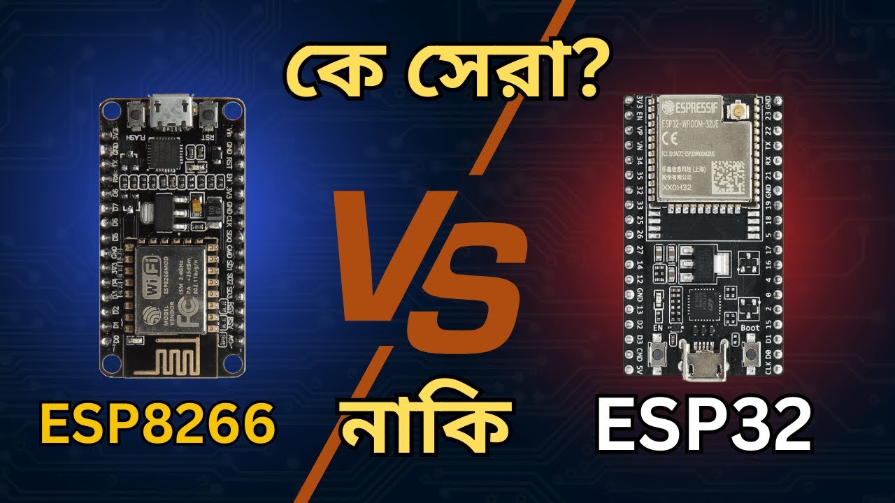
⚔ ESP8266 vs ESP32 vs ESP32-S3 — Full Comparison
Side-by-side comparison to help you pick the right board for your project.
| Feature | BEST VALUE ESP8266 NodeMCU V3 Type-C | MID-RANGE ESP32 Classic Dev Board | FLAGSHIP ESP32-S3 N16R8 |
|---|---|---|---|
| CPU | Single L106 160MHz | Dual LX6 240MHz | Dual LX7 240MHz |
| Flash | 4 MB | 4 MB | 16 MB |
| RAM | 160 KB SRAM | 520 KB SRAM | 512 KB + 8 MB PSRAM |
| WiFi | 802.11 b/g/n | 802.11 b/g/n | 802.11 b/g/n |
| Bluetooth | ❌ None | BT 4.2 + BLE | BT 5.0 LE + LR |
| GPIO Pins | 17 (11 usable) | 34 | 45 |
| ADC | 1× 10-bit | 18× 12-bit | 20× 12-bit |
| Native USB | ❌ No | ❌ No | ✅ USB OTG |
| AI Acceleration | ❌ None | ❌ None | ✅ 128-bit SIMD |
| Deep Sleep | 20 µA | 10 µA | 8 µA |
| Price (Dream RC BD) | 325 BDT 💰 | ~500 BDT | 839 BDT |
| Best For | WiFi IoT, beginners | WiFi + BLE projects | AI, camera, USB HID |
🔧 Full Features & Specifications
🔧 CH340 Driver — Download & Install Guide
Your PC needs the CH340 USB-to-Serial driver to detect the board. Without it no COM port will appear and you cannot upload any code.
Download CH340 Driver (Official WCH)
Download the CH341SER driver package directly from WCH (Nanjing Qinheng) — the chip manufacturer.
Run the Installer
Run CH341SER.EXE → click INSTALL → wait for “Driver install success” message. Works on Windows 7/8/10/11. Mac and Linux usually auto-detect.
Verify the COM Port Appears
Plug Type-C cable → open Device Manager → expand Ports (COM & LPT) → look for USB-SERIAL CH340 (COM X). Note the COM number for Arduino IDE.
Install ESP8266 Board Package in Arduino IDE
File → Preferences → paste this in Additional Boards Manager URLs:http://arduino.esp8266.com/stable/package_esp8266com_index.json
Then Tools → Board → Boards Manager → search esp8266 → install esp8266 by ESP8266 Community.
⚙ Arduino IDE Settings — Exact Values for ESP8266 NodeMCU
Wrong settings are the #1 cause of upload failures and mysterious crashes. Use these exact values every time:
💡 Speed Tip: 160 MHz uses slightly more power but doubles processing speed — great for web servers and JSON parsing.
💻 Code Examples — Copy-Paste + Free .ino Downloads
Four ready-to-upload Arduino sketches. Each has a Download .ino button that saves the file directly to your computer.
🩺 Troubleshooting — Common Issues & Fixes
❓ Frequently Asked Questions
📚 Learn More — ESP8266 Guides & Project Tutorials
Bought your ESP8266 NodeMCU and ready to start building? These Dream RC guides take you from first setup all the way to advanced IoT, home automation, and sensor network projects:
🔗 Need More Power? Upgrade to ESP32
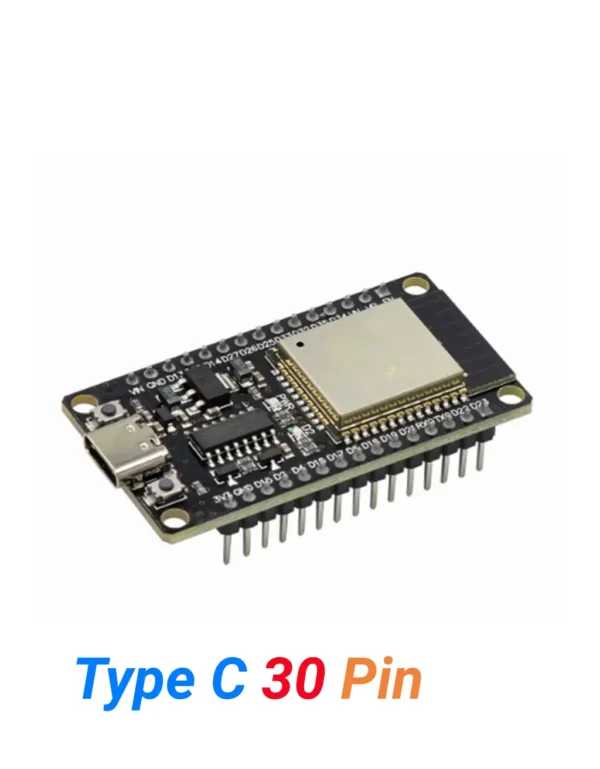
ESP32 Type-C (30 Pins)
Need Bluetooth alongside WiFi? The ESP32 Type-C 30 Pin gives you dual-core 240MHz, WiFi + Bluetooth 4.2 + BLE all in one board — the natural upgrade from ESP8266.
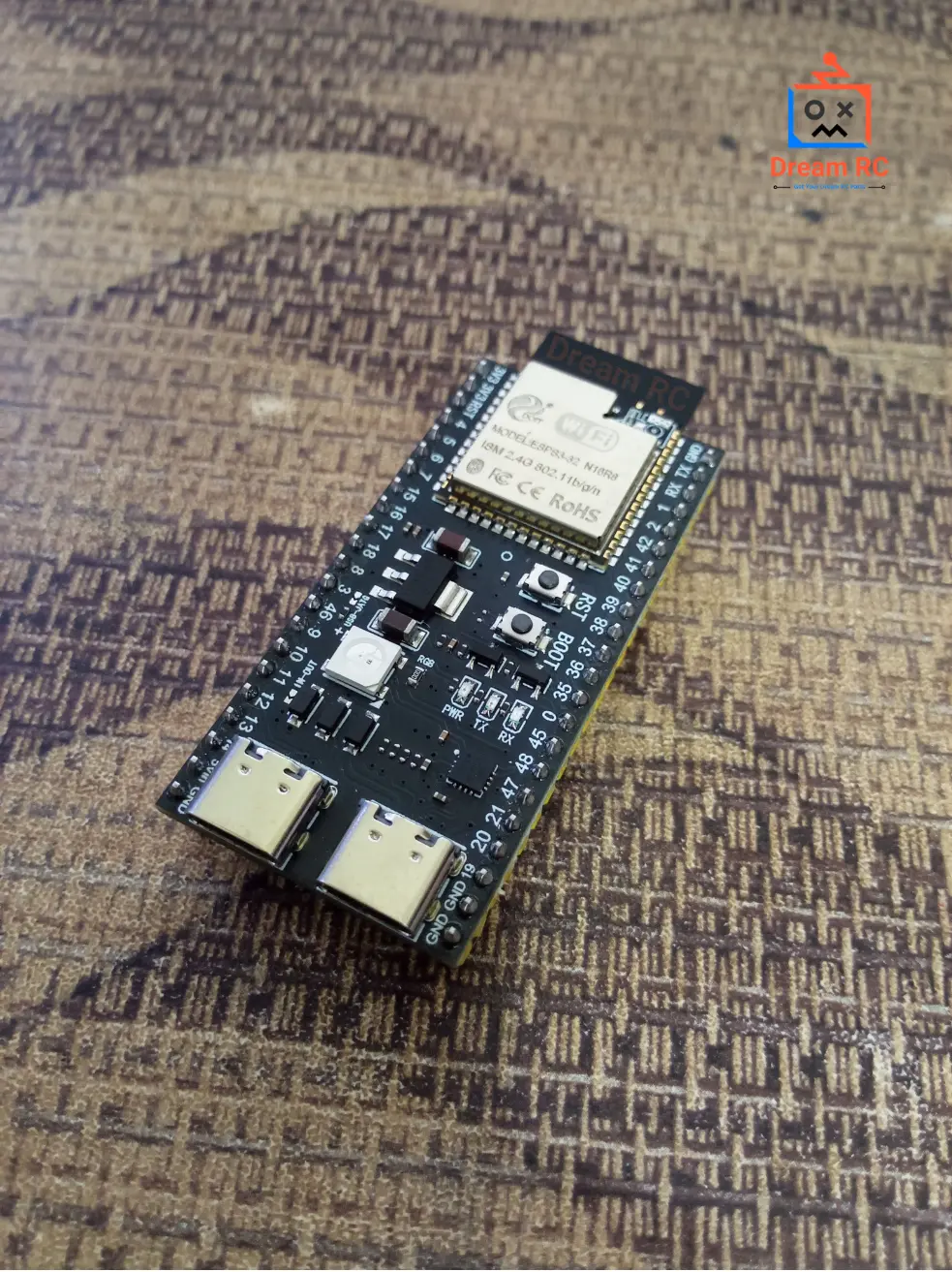
ESP32-S3 WROOM-1 N16R8
Want maximum power? The ESP32-S3 N16R8 adds 16MB Flash, 8MB PSRAM, BT 5.0, and AI/ML acceleration — perfect for camera, AI vision and advanced IoT builds.
📦 Package Includes
1 × ESP8266 NodeMCU V3 Type-C Development Board
Pre-soldered (welded) pin headers included. USB cable and accessories not included.
💬 ESP8266 NodeMCU Price in BD & Why Buy From Dream RC?
The ESP8266 NodeMCU V3 Type-C price in BD is 325 BDT. Buy from Dream RC — Bangladesh’s trusted source for development boards, IoT modules, and electronics components at the best price nationwide.
This board comes with pre-soldered headers, genuine CH340C chip, USB Type-C connector, 4 MB flash, and full WiFi 802.11 b/g/n — ready to use out of the box. The cheapest and most beginner-friendly way to add WiFi to any project. Order with confidence — Cash on Delivery available everywhere in Bangladesh.
✅ COD Available
Pay after receiving
⚡ Fast Dispatch
Quick processing time
🚚 Inside Dhaka
69 BDT — within 24 hrs
🚕 Outside Dhaka
129 BDT — 24 to 72 hrs
Reviews
There are no reviews yet.